다중 선형 액추에이터 간의 동기식 동작은 일부 고객 애플리케이션의 성공에 중요 할 수 있습니다. 하나는 트랩 도어를 여는 두 개의 선형 액추에이터입니다. 이를 달성하려면 전용 Firgelli를 사용하는 것이 좋습니다. 동기식 컨트롤 박스 FA-SYNC-2 및 FA-SYNC-4. 그러나 일부 DIY 사용자와 해커는 Arduino와 같은 마이크로 컨트롤러가 제공하는 자유를 선호하고 대신 자체 동기 제어 프로그램을 작성하는 것을 선호합니다. 이 자습서는 다음을 사용하여이를 달성하는 방법에 대한 개요를 제공하는 것을 목표로합니다. 광학 시리즈 선형 액추에이터.
머리말
이 가이드는 Arduino를 사용하여 동기 제어를 달성하는 데 필요한 단계를 엄격하게 처리하는 것이 아니라 사용자 지정 프로그램을 작성하는 데 도움이되는 광범위한 개요입니다. 이 튜토리얼은 고급이며 Arduino 하드웨어, 소프트웨어에 이미 익숙하고 이상적으로는 펄스 폭 변조 (PWM) 신호, 인터럽트 서비스 루틴 (ISR), 센서 디 바운싱 및 모터 인코더에 대한 경험이 있다고 가정합니다. 이 튜토리얼에서 제공하는 예제는 기본 비례 제어기입니다. 다음 예에서는 PID 제어 루프 구현 및 2 개 이상의 선형 액추에이터로 확장하는 등 많은 개선 사항을 구현할 수 있습니다. Google은 Arduino 애플리케이션에 대한 기술 지원을 제공 할 리소스가 없으며 공개적으로 사용 가능한 자습서 외부에서 코드 또는 배선 다이어그램을 디버그, 편집, 제공하지 않습니다.
동기 제어 개요
동기 제어는 두 개의 선형 액추에이터의 길이를 비교하고 속도를 비례 적으로 조정하여 이루어집니다. 한 액추에이터가 다른 액추에이터보다 빠르게 움직이기 시작하면 속도를 늦 춥니 다. 내장 된 광학 인코더를 통해 선형 액추에이터의 위치를 읽을 수 있습니다. 광학 인코더는 DC 모터에 연결된 10 개의 구멍이있는 작은 플라스틱 디스크로 모터가 회전 할 때 플라스틱 디스크도 마찬가지입니다. 적외선 LED는 플라스틱 디스크를 향하여 빛이 회전 할 때 광 디스크의 구멍을 통해 전송되거나 디스크의 플라스틱에 의해 차단됩니다. 디스크 반대편에있는 적외선 센서는 빛이 구멍을 통해 투과 될 때이를 감지하여 구형파 신호를 출력합니다. 수신기가 감지하는 펄스 수를 세어 모터의 RPM과 선형 액추에이터가 이동 한 거리를 모두 계산할 수 있습니다. 35lb 광학 선형 액추에이터에는 인치당 50 (+/- 5) 광학 펄스가있는 반면 200lb 및 400lb 액추에이터는 모두 인치당 100 (+/- 5) 펄스를 가지고 있습니다. 각 선형 액추에이터가 얼마나 멀리 확장되었는지를 비교하여 두 액추에이터의 속도를 비례 적으로 조정할 수 있으므로 확장하는 동안 항상 동일한 길이를 유지할 수 있습니다.
필수 구성 요소
- 두 개의 광학 선형 액추에이터
- 2 개의 IBT-2 모터 드라이버
- Arduino Uno
- 12V 전원
- 순간 버튼 3 개 (Firgelli에서 판매하지 않음)
- 추가 배선
배선도
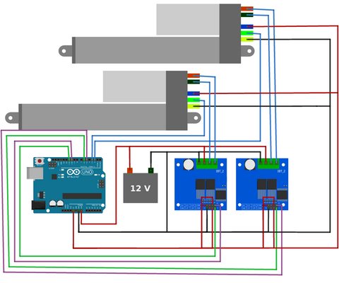
위의 배선 연결을하십시오. 선형 액추에이터에서 나오는 와이어 색상을 항상 확인하십시오. 색상 규칙이 위 다이어그램에 표시된 것과 다를 수 있습니다. 디지털 핀 7, 8, 9 및 GND 사이에 연결된 3 개의 순간 버튼을 간과하지 않도록주의하십시오.
빠른 튜토리얼
두 개의 선형 액추에이터를 동기식으로 이동하려면 다음 단계를 따르십시오.
- 배선도에 표시된대로 연결하십시오.
- 아래의 첫 번째 프로그램을 업로드하고 실행하십시오.
- 이 프로그램에서 출력 한 두 값을 아래 두 번째 프로그램의 23 행에 복사합니다.
- 두 번째 프로그램을 업로드하고 실행합니다.
- 변수 K_p (37 행, 두 번째 프로그램)를 변경하여 시스템을 미세 조정하십시오. 이것은 전위차계를 아날로그 핀 A0에 연결하고 코드를 수정하여 전위차계를 읽고 map () 함수를 사용하여 가장 쉽게 수행 할 수 있습니다. K_p = map (analogRead (A0), 0, 1023, 0, 20000);
이 튜토리얼의 나머지 부분에서는 프로그램의 주요 기능 중 일부에 대해 자세히 설명합니다. 다시 한번 우리는 이것이 완전한 튜토리얼이 아니라 자신의 프로그램을 만들 때 고려해야 할 사항에 대한 개요임을 반복합니다.
교정 프로그램 개요
동기 제어가 이루어지기 전에 먼저 시스템을 보정해야합니다. 여기에는 제품 사양에 명시된대로 1 인치당 (+/- 5) 펄스의 허용 오차가 있기 때문에 작동주기 당 펄스 수를 계산하는 것이 포함됩니다. 아래 프로그램을 업로드하고 실행하십시오. 이 프로그램은 액추에이터 (라인 53)를 완전히 후퇴시키고 광학 펄스 카운터 변수를 0으로 설정 한 다음 완전히 확장되고 완전히 후퇴합니다 (각각 라인 63 및 74). 이 작동주기 동안 펄스 수는 인터럽트 서비스 루틴 (ISR), 라인 153 및 166에 의해 계산됩니다. 작동주기가 완료되면 평균 펄스 수가 출력됩니다 (88 행). 나중에이 값을 기록해 두십시오.
https://gist.github.com/Will-Firgelli/89978da2585a747ef5ff988b2fa53904
/* Written by Firgelli Automations
 * Limited or no support: we do not have the resources for Arduino code support
 * This code exists in the public domain
 *
 * Program requires two (or more) of our supported linear actuators:
 * FA-OS-35-12-XX
 * FA-OS-240-12-XX
 * FA-OS-400-12-XX
 * Products available for purchase at https://www.firgelliauto.com/collections/linear-actuators/products/optical-sensor-actuators
 */

#include <elapsedMillis.h>
elapsedMillis timeElapsed;

#define numberOfActuators 2
int RPWM[numberOfActuators]={6, 11}; //PWM signal right side
int LPWM[numberOfActuators]={5,10};
int opticalPins[numberOfActuators]={2,3}; //connect optical pins to interrupt pins on Arduino. More information: https://www.arduino.cc/reference/en/language/functions/external-interrupts/attachinterrupt/
volatile long lastDebounceTime_0=0; //timer for when interrupt was triggered
volatile long lastDebounceTime_1=0;

int Speed = 255; //choose any speed in the range [0, 255]

#define falsepulseDelay 20 //noise pulse time, if too high, ISR will miss pulses.
volatile int counter[numberOfActuators]={};
volatile int prevCounter[numberOfActuators]={};
int Direction; //-1 = retracting
               // 0 = stopped
               // 1 = extending

int extensionCount[numberOfActuators] = {};
int retractionCount[numberOfActuators] = {};
int pulseTotal[numberOfActuators]={}; //stores number of pulses in one full extension/actuation

void setup(){
  for(int i=0; i<numberOfActuators; i++){
    pinMode(RPWM[i],OUTPUT);
    pinMode(LPWM[i], OUTPUT);
    pinMode(opticalPins[i], INPUT_PULLUP);
    counter[i]=0; //initialize variables as array of zeros
    prevCounter[i]=0;
    extensionCount[i] = 0;
    retractionCount[i] = 0;
    pulseTotal[i] = 0;
  }
  attachInterrupt(digitalPinToInterrupt(opticalPins[0]), count_0, RISING);
  attachInterrupt(digitalPinToInterrupt(opticalPins[1]), count_1, RISING);

  Serial.begin(9600);
  Serial.println("Initializing calibration");
  Serial.println("Actuator retracting...");
  Direction = -1;
  moveTillLimit(Direction, 255);
  Serial.println("Actuator fully retracted");
  delay(1000);

  for(int i=0; i<numberOfActuators; i++){
    Serial.print("\t\t\t\tActuator ");
    Serial.print(i);
  }

  Direction = 1;
  moveTillLimit(Direction, 255); //extend fully and count pulses
  Serial.print("\nExtension Count:");
  for(int i=0; i<numberOfActuators; i++){
  extensionCount[i]=counter[i];
  Serial.print("\t\t");
  Serial.print(extensionCount[i]);
  Serial.print("\t\t\t");
  }
  delay(1000);

  Direction = -1;
  moveTillLimit(Direction, 255); //retract fully and count pulses
  Serial.print("\nRetraction Count:");
  for(int i=0; i<numberOfActuators; i++){
  retractionCount[i]=counter[i];
  Serial.print("\t\t");
  Serial.print(abs(retractionCount[i]));
  Serial.print("\t\t\t");
  }
  Serial.print("\n");

  for(int i=0; i<numberOfActuators; i++){
    Serial.print("\nActuator ");
    Serial.print(i);
    Serial.print(" average pulses: ");
    pulseTotal[i]=(extensionCount[i]+abs(retractionCount[i]))/2; //takes the average of measurements
    Serial.print(pulseTotal[i]);
  }
  Serial.println("\n\nEnter these values in the synchronous control progam.");
}

void loop() {
}

void moveTillLimit(int Direction, int Speed){
  //this function moves the actuator to one of its limits
  for(int i = 0; i < numberOfActuators; i++){
    counter[i] = 0; //reset counter variables
    prevCounter[i] = 0;
  }
  do {
    for(int i = 0; i < numberOfActuators; i++) {
      prevCounter[i] = counter[i];
    }
    timeElapsed = 0;
    while(timeElapsed < 200){ //keep moving until counter remains the same for a short duration of time
      for(int i = 0; i < numberOfActuators; i++) {
        driveActuator(i, Direction, Speed);
      }
    }
  } while(compareCounter(prevCounter, counter)); //loop until all counts remain the same
}

bool compareCounter(volatile int prevCounter[], volatile int counter[]){
  //compares two arrays and returns false when every element of one array is the same as its corresponding indexed element in the other array
  bool areUnequal = true;
  for(int i = 0; i < numberOfActuators; i++){
    if(prevCounter[i] == counter[i]){
      areUnequal = false;
    }
    else{ //if even one pair of elements are unequal the entire function returns true
      areUnequal = true;
      break;
    }
  }
  return areUnequal;
}

void driveActuator(int Actuator, int Direction, int Speed){
  int rightPWM=RPWM[Actuator];
  int leftPWM=LPWM[Actuator];

  switch(Direction){
  case 1: //extension
    analogWrite(rightPWM, Speed);
    analogWrite(leftPWM, 0);
  break;

  case 0: //stopping
    analogWrite(rightPWM, 0);
    analogWrite(leftPWM, 0);
  break;

  case -1: //retraction
    analogWrite(rightPWM, 0);
    analogWrite(leftPWM, Speed);
  break;
  }
}

void count_0(){
  //This interrupt function increments a counter corresponding to changes in the optical pin status
  if ((millis() - lastDebounceTime_0) > falsepulseDelay) { //reduce noise by debouncing IR signal
    lastDebounceTime_0 = millis();
    if(Direction==1){
      counter[0]++;
    }
    if(Direction==-1){
      counter[0]--;
    }
  }
}

void count_1(){
  if ((millis() - lastDebounceTime_1) > falsepulseDelay) {
    lastDebounceTime_1 = millis();
    if(Direction==1){
      counter[1]++;
    }
    if(Direction==-1){
      counter[1]--;
    }
  }
}
동기식 프로그램 개요
동기 제어 프로그램을 업로드하기 전에 먼저 보정 프로그램에서 출력 한 값을 23 행에 복사하고 현재 배열 : {908, 906}을 자신의 값으로 바꿔야합니다. 또한 35lb 선형 액추에이터를 사용하는 경우 29 행의 변수 값을 20 밀리 초에서 8 밀리 초로 변경해야합니다.
한 번 완전히 후퇴 한 후 (원점 식별을 위해) 확장, 후퇴 및 중지 명령에 해당하는 세 개의 버튼을 눌러 두 선형 액추에이터를 동시에 이동할 수 있습니다. 액추에이터는 상대 펄스 카운터를 비교하고 항상 동기 상태를 유지하도록 속도를 조정하여 고르지 않은 부하에서도 동기 상태를 유지합니다. 현재 프로그램은 평형 주변에서 오버 슈트 및 진동의 영향을 받기 때문에 단순한 비례 컨트롤러 라인 93을 구현합니다. 37 행에 정의 된 K_p 변수를 변경하여이를 조정할 수 있습니다.이것은 전위차계를 아날로그 핀 A0에 연결하고 코드를 수정하여 전위차계를 읽고 map () 함수를 사용하여 가장 쉽게 수행 할 수 있습니다. K_p = map (analogRead (A0), 0, 1023, 0, 20000);
최상의 결과를 얻으려면 비례 컨트롤러를 제거하고 PID 제어 루프를 구현하는 것이 좋습니다. 그러나 이것은이 입문 자습서의 범위를 벗어나고 의도적으로 생략되었습니다.
https://gist.github.com/Will-Firgelli/44a14a4f3cac3209164efe8abe3285b6
/* Written by Firgelli Automations
 * Limited or no support: we do not have the resources for Arduino code support
 * This code exists in the public domain
 *
 */

#include <elapsedMillis.h>
elapsedMillis timeElapsed;

#define numberOfActuators 2
int downPin = 7;
int stopPin = 8;
int upPin = 9;
int RPWM[numberOfActuators]={6, 11};                                  //PWM signal right side
int LPWM[numberOfActuators]={5,10};
int opticalPins[numberOfActuators]={2,3};                             //connect optical pins to interrupt pins on Arduino. More information: https://www.arduino.cc/reference/en/language/functions/external-interrupts/attachinterrupt/
volatile unsigned long lastDebounceTime[numberOfActuators]={0,0};     //timer for when interrupt is triggered
int pulseTotal[numberOfActuators]={908, 906};                         //values found experimentally by first running two-optical-actuators-sync-calibration.ino

int desiredSpeed=255;
int adjustedSpeed;
int Speed[numberOfActuators]={};

#define falsepulseDelay 20                                            //noise pulse time, if too high, ISR will miss pulses. If using 35lb actuator, set to 8ms
volatile int counter[numberOfActuators]={};
volatile int prevCounter[numberOfActuators]={};
volatile float normalizedPulseCount[numberOfActuators]={};
int Direction;                                                        //-1 = retracting
                                                                      // 0 = stopped
                                                                      // 1 = extending
float error;
int K_p=12000;                                                        //optimized experimentally. adjust this to fine tune your system
int laggingIndex, leadingIndex;                                       //index of the slowest/fastest actuator

void setup(){
  pinMode(stopPin, INPUT_PULLUP);
  pinMode(downPin, INPUT_PULLUP);
  pinMode(upPin, INPUT_PULLUP);
  for(int i=0; i<numberOfActuators; i++){
    pinMode(RPWM[i],OUTPUT);
    pinMode(LPWM[i], OUTPUT);
    pinMode(opticalPins[i], INPUT_PULLUP);
    Speed[i]=desiredSpeed;
  }
  attachInterrupt(digitalPinToInterrupt(opticalPins[0]), count_0, RISING);
  attachInterrupt(digitalPinToInterrupt(opticalPins[1]), count_1, RISING);
  Serial.begin(9600);
  Serial.println("Calibrating the origin");
  Serial.println("Actuator retracting...");
  Direction = -1;
  moveTillLimit(Direction, 255);
  for(int i=0; i<numberOfActuators; i++){
    counter[i]=0;                                                     //reset variables
    prevCounter[i]=0;
    normalizedPulseCount[i] = 0;
  }
  delay(1000);
  Serial.println("Actuator fully retracted");
}

void loop() {
  checkButtons();

  if(Direction==1){                                                   //based on direction of motion identify the leading and lagging actuator by comparing pulse counts
    if(normalizedPulseCount[0] < normalizedPulseCount[1]){
      laggingIndex = 0;
      leadingIndex = 1;
    }
    else{
      laggingIndex = 1;
      leadingIndex = 0;
    }
  }
  else if(Direction==-1){
    if(normalizedPulseCount[0] > normalizedPulseCount[1]){
      laggingIndex = 0;
      leadingIndex = 1;
    }
    else{
      laggingIndex = 1;
      leadingIndex = 0;
    }
  }

  error=abs(normalizedPulseCount[laggingIndex]-normalizedPulseCount[leadingIndex]);
  if(Direction!=0){
    adjustedSpeed=desiredSpeed-int(error*K_p);
    Speed[leadingIndex]=constrain(adjustedSpeed, 0, 255);               //slow down fastest actuator
    Speed[laggingIndex]=desiredSpeed;
  }
  for(int i=0; i<numberOfActuators; i++){
    Serial.print("  ");
    Serial.print(Speed[i]);
    Serial.print("  ");
    Serial.print(normalizedPulseCount[i]*1000);
    driveActuator(i, Direction, Speed[i]);
  }
  Serial.println();
}

void checkButtons(){
  //latching buttons: direction remains the same when let go
  if(digitalRead(upPin)==LOW){ Direction=1; }                           //check if extension button is pressed
  if(digitalRead(downPin)==LOW){ Direction=-1; }
  if(digitalRead(stopPin)==LOW){ Direction=0; }
}

void moveTillLimit(int Direction, int Speed){
  //function moves the actuator to one of its limits
  for(int i = 0; i < numberOfActuators; i++){
    counter[i] = 0;                                                     //reset counter variables
    prevCounter[i] = 0;
  }
  do {
    for(int i = 0; i < numberOfActuators; i++) {
      prevCounter[i] = counter[i];
    }
    timeElapsed = 0;
    while(timeElapsed < 200){                                           //keep moving until counter remains the same for a short duration of time
      for(int i = 0; i < numberOfActuators; i++) {
        driveActuator(i, Direction, Speed);
      }
    }
  } while(compareCounter(prevCounter, counter));                        //loop until all counters remain the same
}

bool compareCounter(volatile int prevCounter[], volatile int counter[]){
  //compares two arrays and returns false when every element of one array is the same as its corresponding indexed element in the other array
  bool areUnequal = true;
  for(int i = 0; i < numberOfActuators; i++){
    if(prevCounter[i] == counter[i]){
      areUnequal = false;
    }
    else{                                                               //if even one pair of elements are unequal the entire function returns true
      areUnequal = true;
      break;
    }
  }
  return areUnequal;
}

void driveActuator(int Actuator, int Direction, int Speed){
  int rightPWM=RPWM[Actuator];
  int leftPWM=LPWM[Actuator];
  switch(Direction){
    case 1:       //extension
      analogWrite(rightPWM, Speed);
      analogWrite(leftPWM, 0);
      break;
    case 0:       //stopping
      analogWrite(rightPWM, 0);
      analogWrite(leftPWM, 0);
      break;
    case -1:      //retraction
      analogWrite(rightPWM, 0);
      analogWrite(leftPWM, Speed);
      break;
  }
}

void count_0(){
  //This interrupt function increments a counter corresponding to changes in the optical pin status
  if ((millis() - lastDebounceTime[0]) > falsepulseDelay) {             //reduce noise by debouncing IR signal with a delay
    lastDebounceTime[0] = millis();
    if(Direction==1){
      counter[0]++;
    }
    if(Direction==-1){
      counter[0]--;
    }
    normalizedPulseCount[0]=float(counter[0])/float(pulseTotal[0]);
  }
}

void count_1(){
  if ((millis() - lastDebounceTime[1]) > falsepulseDelay) {
    lastDebounceTime[1] = millis();
    if(Direction==1){
      counter[1]++;
    }
    if(Direction==-1){
      counter[1]--;
    }
    normalizedPulseCount[1]=float(counter[1])/float(pulseTotal[1]);
  }
}
Bullet 36 및 Bullet 50 액추에이터를 동기식으로 사용
광학 시리즈 선형 액추에이터 외에도 엔코더가 내장 된 두 가지 선형 액추에이터 인 Bullet 36 Cal을 제공합니다. 및 Bullet 50 Cal은 모두 내부 쿼드 러처 홀 효과 인코더가 있습니다. 홀 효과 인코더는 광학 인코더와 동일한 원리로 작동하지만 빛을 사용하는 대신 자기를 사용합니다. 또한 구적 엔코더이기 때문에 각각 90도 위상차가있는 두 개의 신호 출력이 있습니다. 따라서 4 개 이상의 인터럽트 핀 (Arduino Uno에는 2 개만 있음)이있는 Arduino 보드를 사용하고 액추에이터 당 2 개의 신호에서 입력을 처리하도록 코드를 수정해야합니다. 또한 디 바운스 시간 변수 인 falsepulseDelay를 K_p와 함께 조정해야합니다.
자신 만의 프로그램 작성을위한 팁
2 개 이상의 선형 액추에이터
두 개 이상의 선형 액추에이터를 사용할 때 Arduino Uno는 두 개의 인터럽트 핀만 사용할 수 있으므로 더 이상 작동하지 않습니다. 적절한 수의 인터럽트 핀을 사용할 수있는 Arduino 보드를 사용해야합니다. 자세한 정보 : https://www.arduino.cc/reference/en/language/functions/external-interrupts/attachinterrupt/
둘째, 효율성을 위해 배열 및 for () 루프를 사용하여 프로그래밍을 벡터화하여 각 액추에이터를 반복하는 것이 좋습니다.
디 바운싱
많은 센서와 마찬가지로 수신 거부 신호를 인식하는 것이 중요합니다. 기계식 스위치와 마찬가지로 인코더는 바운스로 인해 어려움을 겪을 수 있습니다. 위의 예에서 바운싱 프로세스는 간단한 지연(falsepulseDelay 변수에 의해 정의됨)에 의해 처리되었으며, 수신 대기 노이즈를 필터링하기 위해 수행하는 소프트웨어 변경 또는 물리적으로 회로에서 이를 처리하는 것이 중요합니다.
롤 오버 처리
코드를 수정하는 경우 밀리() 함수를 처리할 때 롤오버에 유의해야 합니다. 밀리() 및 마지막DebounceTime 배열은 서명되지 않은 긴 변수로 선언되어 최대 4,294,967,295(32^2-1)의 값을 저장할 수 있습니다. 이는 대략 49.7일의 롤오버 기간을 변환합니다. 현재 프로그램은 ISR(중단 서비스 루틴) 기능에서 롤오버를 처리하도록 설계되었지만, count_0 count_1 이 프로그램을 수정하면 가변 롤오버를 올바르게 처리해야 하며, 49.7일 연속 으로 프로그램이 중단됩니다. 자세한 내용은 다음을 참조하십시오. https://www.norwegiancreations.com/2018/10/arduino-tutorial-avoiding-the-overflow-issue-when-using-millis-and-micros/


