複数のリニアアクチュエータ間の同期運動は、一部の顧客アプリケーションの成功に不可欠である可能性があります。一般的なものの1つは、トラップドアを開く2つのリニアアクチュエータです。これを実現するには、専用のFirgelliを使用することをお勧めします 同期制御ボックスFA-SYNC-2およびFA-SYNC-4。ただし、一部のDIYやハッカーは、Arduinoなどのマイクロコントローラーが提供する自由を好み、代わりに独自の同期制御プログラムを作成することを好みます。このチュートリアルは、を使用してこれを実現する方法の概要を提供することを目的としています。 オプティカルシリーズリニアアクチュエータ.
序文
このチュートリアルは、Arduinoとの同期制御を実現するために必要な手順の厳密な取り扱いではなく、独自のカスタムプログラムの作成を支援するための大まかな概要です。 このチュートリアルは高度であり、Arduinoのハードウェア、ソフトウェアに精通しており、理想的にはパルス幅変調(PWM)信号、割り込みサービスルーチン(ISR)、センサーのデバウンス、およびモーターエンコーダーの経験があることを前提としています。 このチュートリアルで提供される例は、プリミティブ比例コントローラーです。次の例では、PID制御ループの実装や3つ以上のリニアアクチュエータへのスケーリングなど、多くの改善を実装できます。 Arduinoアプリケーションのテクニカルサポートを提供するためのリソースがなく、これらの公開されているチュートリアル以外でデバッグ、編集、コードまたは配線図を提供しないことに注意してください。
概要同期制御
同期制御は、2つのリニアアクチュエータの長さを比較し、それに比例して速度を調整することによって実現されます。あるアクチュエータが別のアクチュエータよりも速く動き始めると、速度が低下します。内蔵の光学式エンコーダを介してリニアアクチュエータの位置を読み取ることができます。光学式エンコーダは、DCモーターに接続された、10個の穴が開いた小さなプラスチックディスクで、モーターが回転するとプラスチックディスクも回転します。赤外線LEDがプラスチックディスクに向けられているため、光が回転すると、光ディスクの穴を透過するか、ディスクのプラスチックによってブロックされます。ディスクの反対側にある赤外線センサーは、光が穴を透過したことを検出し、方形波信号を出力します。レシーバーが検出するパルス数をカウントすることにより、モーターのRPMとリニアアクチュエーターが移動した距離の両方を計算できます。 35ポンドの光リニアアクチュエータは1インチの移動あたり50(+/- 5)の光パルスを持ち、200ポンドと400ポンドのアクチュエータは両方とも1インチあたり100(+/- 5)のパルスを持ちます。各リニアアクチュエータがどれだけ伸びているかを比較することにより、2つのアクチュエータの速度を比例的に調整して、伸びている間、常に同じ長さに留まるようにすることができます。
必要なコンポーネント
- 2つの光学式リニアアクチュエータ
- 2つのIBT-2モータードライバー
- Arduino Uno
- 12V電源
- 3つの瞬間的なボタン(Firgelliは販売していません)
- 追加の配線
配線図
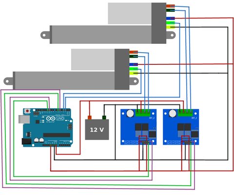
上記の配線接続を行ってください。リニアアクチュエータから出てくるワイヤの色を常に確認してください。色の規則が上の図に示されているものと異なる場合があります。
クイックチュートリアル
2つのリニアアクチュエータを同期させたいだけの場合は、次の手順に従ってください。
- 配線図のように接続してください。
- 以下の最初のプログラムをアップロードして実行します。
- このプログラムによって出力された2つの値を、以下の2番目のプログラムの23行目にコピーします。
- 2番目のプログラムをアップロードして実行します。
- 変数K_pを変更してシステムを微調整します(37行目、2番目のプログラム)。これは、ポテンショメータをアナログピンA0に接続し、コードを変更してポテンショメータを読み取り、map()関数を使用することで最も簡単に実行できます。K_p= map(analogRead(A0)、0、1023、0、20000);
このチュートリアルの残りの部分では、プログラムの主要な機能のいくつかについて詳しく説明します。繰り返しになりますが、これは完全なチュートリアルではなく、独自のプログラムを作成する際に考慮すべき事項の概要です。
校正プログラムの概要
同期制御を実現する前に、まずシステムを校正する必要があります。製品仕様に記載されているように、移動1インチあたり(+/- 5)パルスの許容誤差があるため、これには、作動サイクルあたりのパルス数のカウントが含まれます。以下のプログラムをアップロードして実行します。このプログラムは、アクチュエータを完全に収縮させ(53行目)、光パルスカウンタ変数をゼロに設定してから、完全に伸長および完全に収縮させます(それぞれ63行目と74行目)。この作動サイクル中、パルス数は割り込みサービスルーチン(ISR)の153行目と166行目でカウントされます。作動サイクルが完了すると、平均パルス数が出力されます(88行目)。後で使用するためにこれらの値をメモしてください。
https://gist.github.com/Will-Firgelli/89978da2585a747ef5ff988b2fa53904
/* Written by Firgelli Automations
 * Limited or no support: we do not have the resources for Arduino code support
 * This code exists in the public domain
 *
 * Program requires two (or more) of our supported linear actuators:
 * FA-OS-35-12-XX
 * FA-OS-240-12-XX
 * FA-OS-400-12-XX
 * Products available for purchase at https://www.firgelliauto.com/collections/linear-actuators/products/optical-sensor-actuators
 */

#include <elapsedMillis.h>
elapsedMillis timeElapsed;

#define numberOfActuators 2
int RPWM[numberOfActuators]={6, 11}; //PWM signal right side
int LPWM[numberOfActuators]={5,10};
int opticalPins[numberOfActuators]={2,3}; //connect optical pins to interrupt pins on Arduino. More information: https://www.arduino.cc/reference/en/language/functions/external-interrupts/attachinterrupt/
volatile long lastDebounceTime_0=0; //timer for when interrupt was triggered
volatile long lastDebounceTime_1=0;

int Speed = 255; //choose any speed in the range [0, 255]

#define falsepulseDelay 20 //noise pulse time, if too high, ISR will miss pulses.
volatile int counter[numberOfActuators]={};
volatile int prevCounter[numberOfActuators]={};
int Direction; //-1 = retracting
               // 0 = stopped
               // 1 = extending

int extensionCount[numberOfActuators] = {};
int retractionCount[numberOfActuators] = {};
int pulseTotal[numberOfActuators]={}; //stores number of pulses in one full extension/actuation

void setup(){
  for(int i=0; i<numberOfActuators; i++){
    pinMode(RPWM[i],OUTPUT);
    pinMode(LPWM[i], OUTPUT);
    pinMode(opticalPins[i], INPUT_PULLUP);
    counter[i]=0; //initialize variables as array of zeros
    prevCounter[i]=0;
    extensionCount[i] = 0;
    retractionCount[i] = 0;
    pulseTotal[i] = 0;
  }
  attachInterrupt(digitalPinToInterrupt(opticalPins[0]), count_0, RISING);
  attachInterrupt(digitalPinToInterrupt(opticalPins[1]), count_1, RISING);

  Serial.begin(9600);
  Serial.println("Initializing calibration");
  Serial.println("Actuator retracting...");
  Direction = -1;
  moveTillLimit(Direction, 255);
  Serial.println("Actuator fully retracted");
  delay(1000);

  for(int i=0; i<numberOfActuators; i++){
    Serial.print("\t\t\t\tActuator ");
    Serial.print(i);
  }

  Direction = 1;
  moveTillLimit(Direction, 255); //extend fully and count pulses
  Serial.print("\nExtension Count:");
  for(int i=0; i<numberOfActuators; i++){
  extensionCount[i]=counter[i];
  Serial.print("\t\t");
  Serial.print(extensionCount[i]);
  Serial.print("\t\t\t");
  }
  delay(1000);

  Direction = -1;
  moveTillLimit(Direction, 255); //retract fully and count pulses
  Serial.print("\nRetraction Count:");
  for(int i=0; i<numberOfActuators; i++){
  retractionCount[i]=counter[i];
  Serial.print("\t\t");
  Serial.print(abs(retractionCount[i]));
  Serial.print("\t\t\t");
  }
  Serial.print("\n");

  for(int i=0; i<numberOfActuators; i++){
    Serial.print("\nActuator ");
    Serial.print(i);
    Serial.print(" average pulses: ");
    pulseTotal[i]=(extensionCount[i]+abs(retractionCount[i]))/2; //takes the average of measurements
    Serial.print(pulseTotal[i]);
  }
  Serial.println("\n\nEnter these values in the synchronous control progam.");
}

void loop() {
}

void moveTillLimit(int Direction, int Speed){
  //this function moves the actuator to one of its limits
  for(int i = 0; i < numberOfActuators; i++){
    counter[i] = 0; //reset counter variables
    prevCounter[i] = 0;
  }
  do {
    for(int i = 0; i < numberOfActuators; i++) {
      prevCounter[i] = counter[i];
    }
    timeElapsed = 0;
    while(timeElapsed < 200){ //keep moving until counter remains the same for a short duration of time
      for(int i = 0; i < numberOfActuators; i++) {
        driveActuator(i, Direction, Speed);
      }
    }
  } while(compareCounter(prevCounter, counter)); //loop until all counts remain the same
}

bool compareCounter(volatile int prevCounter[], volatile int counter[]){
  //compares two arrays and returns false when every element of one array is the same as its corresponding indexed element in the other array
  bool areUnequal = true;
  for(int i = 0; i < numberOfActuators; i++){
    if(prevCounter[i] == counter[i]){
      areUnequal = false;
    }
    else{ //if even one pair of elements are unequal the entire function returns true
      areUnequal = true;
      break;
    }
  }
  return areUnequal;
}

void driveActuator(int Actuator, int Direction, int Speed){
  int rightPWM=RPWM[Actuator];
  int leftPWM=LPWM[Actuator];

  switch(Direction){
  case 1: //extension
    analogWrite(rightPWM, Speed);
    analogWrite(leftPWM, 0);
  break;

  case 0: //stopping
    analogWrite(rightPWM, 0);
    analogWrite(leftPWM, 0);
  break;

  case -1: //retraction
    analogWrite(rightPWM, 0);
    analogWrite(leftPWM, Speed);
  break;
  }
}

void count_0(){
  //This interrupt function increments a counter corresponding to changes in the optical pin status
  if ((millis() - lastDebounceTime_0) > falsepulseDelay) { //reduce noise by debouncing IR signal
    lastDebounceTime_0 = millis();
    if(Direction==1){
      counter[0]++;
    }
    if(Direction==-1){
      counter[0]--;
    }
  }
}

void count_1(){
  if ((millis() - lastDebounceTime_1) > falsepulseDelay) {
    lastDebounceTime_1 = millis();
    if(Direction==1){
      counter[1]++;
    }
    if(Direction==-1){
      counter[1]--;
    }
  }
}
同期プログラムの概要
同期制御プログラムをアップロードする前に、まずキャリブレーションプログラムによって出力された値を23行目にコピーし、現在の配列{908、906}を独自の値に置き換える必要があります。さらに、35ポンドのリニアアクチュエータを使用している場合は、29行目の変数の値を20ミリ秒から8ミリ秒に変更する必要があります。
(原点を特定するために)一度完全に収縮した後、伸長、収縮、および停止コマンドに対応する3つのボタンを押すことにより、両方のリニアアクチュエータを同期して動かすことができます。アクチュエータは、相対的なパルスカウンタを比較し、それらの間の速度を調整して常に同期を維持することにより、不均一な負荷の下でも同期を維持します。現在のプログラムは単純な比例コントローラー、ライン93を実装しているため、平衡の周りでオーバーシュートと振動が発生する可能性があることに注意してください。これは、37行目で定義されている変数K_pを変更することで調整できます。 これは、ポテンショメータをアナログピンA0に接続し、コードを変更してポテンショメータを読み取り、map()関数を使用することで最も簡単に実行できます。K_p= map(analogRead(A0)、0、1023、0、20000);
最良の結果を得るには、比例コントローラーを削除し、PID制御ループを実装することを強くお勧めします。ただし、これはこの入門チュートリアルの範囲を超えており、意図的に省略されています。
https://gist.github.com/Will-Firgelli/44a14a4f3cac3209164efe8abe3285b6
/* Written by Firgelli Automations
 * Limited or no support: we do not have the resources for Arduino code support
 * This code exists in the public domain
 *
 */

#include <elapsedMillis.h>
elapsedMillis timeElapsed;

#define numberOfActuators 2
int downPin = 7;
int stopPin = 8;
int upPin = 9;
int RPWM[numberOfActuators]={6, 11};                                  //PWM signal right side
int LPWM[numberOfActuators]={5,10};
int opticalPins[numberOfActuators]={2,3};                             //connect optical pins to interrupt pins on Arduino. More information: https://www.arduino.cc/reference/en/language/functions/external-interrupts/attachinterrupt/
volatile unsigned long lastDebounceTime[numberOfActuators]={0,0};     //timer for when interrupt is triggered
int pulseTotal[numberOfActuators]={908, 906};                         //values found experimentally by first running two-optical-actuators-sync-calibration.ino

int desiredSpeed=255;
int adjustedSpeed;
int Speed[numberOfActuators]={};

#define falsepulseDelay 20                                            //noise pulse time, if too high, ISR will miss pulses. If using 35lb actuator, set to 8ms
volatile int counter[numberOfActuators]={};
volatile int prevCounter[numberOfActuators]={};
volatile float normalizedPulseCount[numberOfActuators]={};
int Direction;                                                        //-1 = retracting
                                                                      // 0 = stopped
                                                                      // 1 = extending
float error;
int K_p=12000;                                                        //optimized experimentally. adjust this to fine tune your system
int laggingIndex, leadingIndex;                                       //index of the slowest/fastest actuator

void setup(){
  pinMode(stopPin, INPUT_PULLUP);
  pinMode(downPin, INPUT_PULLUP);
  pinMode(upPin, INPUT_PULLUP);
  for(int i=0; i<numberOfActuators; i++){
    pinMode(RPWM[i],OUTPUT);
    pinMode(LPWM[i], OUTPUT);
    pinMode(opticalPins[i], INPUT_PULLUP);
    Speed[i]=desiredSpeed;
  }
  attachInterrupt(digitalPinToInterrupt(opticalPins[0]), count_0, RISING);
  attachInterrupt(digitalPinToInterrupt(opticalPins[1]), count_1, RISING);
  Serial.begin(9600);
  Serial.println("Calibrating the origin");
  Serial.println("Actuator retracting...");
  Direction = -1;
  moveTillLimit(Direction, 255);
  for(int i=0; i<numberOfActuators; i++){
    counter[i]=0;                                                     //reset variables
    prevCounter[i]=0;
    normalizedPulseCount[i] = 0;
  }
  delay(1000);
  Serial.println("Actuator fully retracted");
}

void loop() {
  checkButtons();

  if(Direction==1){                                                   //based on direction of motion identify the leading and lagging actuator by comparing pulse counts
    if(normalizedPulseCount[0] < normalizedPulseCount[1]){
      laggingIndex = 0;
      leadingIndex = 1;
    }
    else{
      laggingIndex = 1;
      leadingIndex = 0;
    }
  }
  else if(Direction==-1){
    if(normalizedPulseCount[0] > normalizedPulseCount[1]){
      laggingIndex = 0;
      leadingIndex = 1;
    }
    else{
      laggingIndex = 1;
      leadingIndex = 0;
    }
  }

  error=abs(normalizedPulseCount[laggingIndex]-normalizedPulseCount[leadingIndex]);
  if(Direction!=0){
    adjustedSpeed=desiredSpeed-int(error*K_p);
    Speed[leadingIndex]=constrain(adjustedSpeed, 0, 255);               //slow down fastest actuator
    Speed[laggingIndex]=desiredSpeed;
  }
  for(int i=0; i<numberOfActuators; i++){
    Serial.print("  ");
    Serial.print(Speed[i]);
    Serial.print("  ");
    Serial.print(normalizedPulseCount[i]*1000);
    driveActuator(i, Direction, Speed[i]);
  }
  Serial.println();
}

void checkButtons(){
  //latching buttons: direction remains the same when let go
  if(digitalRead(upPin)==LOW){ Direction=1; }                           //check if extension button is pressed
  if(digitalRead(downPin)==LOW){ Direction=-1; }
  if(digitalRead(stopPin)==LOW){ Direction=0; }
}

void moveTillLimit(int Direction, int Speed){
  //function moves the actuator to one of its limits
  for(int i = 0; i < numberOfActuators; i++){
    counter[i] = 0;                                                     //reset counter variables
    prevCounter[i] = 0;
  }
  do {
    for(int i = 0; i < numberOfActuators; i++) {
      prevCounter[i] = counter[i];
    }
    timeElapsed = 0;
    while(timeElapsed < 200){                                           //keep moving until counter remains the same for a short duration of time
      for(int i = 0; i < numberOfActuators; i++) {
        driveActuator(i, Direction, Speed);
      }
    }
  } while(compareCounter(prevCounter, counter));                        //loop until all counters remain the same
}

bool compareCounter(volatile int prevCounter[], volatile int counter[]){
  //compares two arrays and returns false when every element of one array is the same as its corresponding indexed element in the other array
  bool areUnequal = true;
  for(int i = 0; i < numberOfActuators; i++){
    if(prevCounter[i] == counter[i]){
      areUnequal = false;
    }
    else{                                                               //if even one pair of elements are unequal the entire function returns true
      areUnequal = true;
      break;
    }
  }
  return areUnequal;
}

void driveActuator(int Actuator, int Direction, int Speed){
  int rightPWM=RPWM[Actuator];
  int leftPWM=LPWM[Actuator];
  switch(Direction){
    case 1:       //extension
      analogWrite(rightPWM, Speed);
      analogWrite(leftPWM, 0);
      break;
    case 0:       //stopping
      analogWrite(rightPWM, 0);
      analogWrite(leftPWM, 0);
      break;
    case -1:      //retraction
      analogWrite(rightPWM, 0);
      analogWrite(leftPWM, Speed);
      break;
  }
}

void count_0(){
  //This interrupt function increments a counter corresponding to changes in the optical pin status
  if ((millis() - lastDebounceTime[0]) > falsepulseDelay) {             //reduce noise by debouncing IR signal with a delay
    lastDebounceTime[0] = millis();
    if(Direction==1){
      counter[0]++;
    }
    if(Direction==-1){
      counter[0]--;
    }
    normalizedPulseCount[0]=float(counter[0])/float(pulseTotal[0]);
  }
}

void count_1(){
  if ((millis() - lastDebounceTime[1]) > falsepulseDelay) {
    lastDebounceTime[1] = millis();
    if(Direction==1){
      counter[1]++;
    }
    if(Direction==-1){
      counter[1]--;
    }
    normalizedPulseCount[1]=float(counter[1])/float(pulseTotal[1]);
  }
}
Bullet36およびBullet50アクチュエータを同期的に使用する
オプティカルシリーズリニアアクチュエータに加えて、エンコーダを内蔵した2つのリニアアクチュエータを提供しています。Bullet36Calです。とBullet50 Calは、どちらも内部直交ホール効果エンコーダーを備えています。ホール効果エンコーダは光学式エンコーダと同じ原理で動作しますが、光を使用する代わりに磁気を利用します。さらに、直交エンコーダであるため、2つの信号出力があり、それぞれが90度位相がずれています。そのため、4つ以上の割り込みピンを備えたArduinoボードを使用し(Arduino Unoには2つしかない)、アクチュエータごとに2つの信号からの入力を処理するようにコードを変更する必要があります。さらに、デバウンス時間変数falsepulseDelayをK_pと一緒に調整する必要があります。
独自のプログラムを作成するためのヒント
3つ以上のリニアアクチュエータ
2つ以上のリニアアクチュエータを使用する場合、Arduino Unoは2つの割り込みピンしか使用できないため、機能しなくなります。適切な数の割り込みピンが使用可能なArduinoボードを使用する必要があります。詳細については、以下を参照してください。 https://www.arduino.cc/reference/en/language/functions/external-interrupts/attachinterrupt/
次に、効率を上げるために、配列とfor()ループを使用してプログラミングをベクトル化し、各アクチュエータを反復処理することをお勧めします。
デバウンス
多くのセンサーと同様に、バウンスする信号を認識することが重要です。メカニカルスイッチと同様に、エンコーダーもバウンドする可能性があります。上記の例では、デバウンスプロセスは単純な遅延(falsepulseDelay変数で定義)によって処理されています。これをソフトウェアの変更で処理するか、バウンスノイズを除去するための物理回路で処理することが重要です。
ロールオーバーの処理
コードを変更する場合は、millis()関数を処理するときにロールオーバーに注意してください。 mills()とlastDebounceTime配列はどちらも、符号なしの長い変数として宣言されています。つまり、最大4,294,967,295(32 ^ 2-1)の値を格納できます。これは、およそ49。7日のロールオーバー期間に相当します。現在のプログラムは、ISR(割り込みサービスルーチン)関数count_0およびcount_1でロールオーバーを処理するように設計されていますが、このプログラムを変更する場合は、変数ロールオーバーを正しく処理するようにしてください。そうしないと、約49。7日間の連続使用後にプログラムがクラッシュします。詳細については、以下を参照してください。 https://www.norwegiancreations.com/2018/10/arduino-tutorial-avoiding-the-overflow-issue-when-using-millis-and-micros/


