- Description
- Specifications
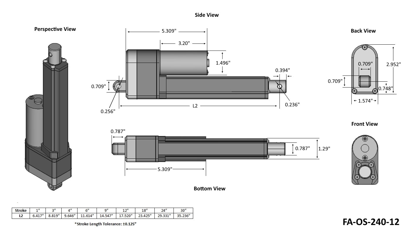
- Technical Drawings
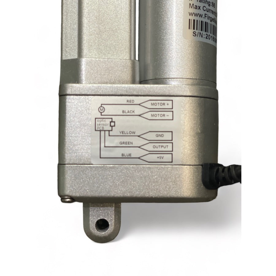
- Wiring Diagram
- Performance Graph
- Product Video
- Comparison Video
- Conversion to Column Actuator video
- 3D Model Downloads (.STEP)
- Wiring Diagram
- Tutorial
Description
***DISCONTINUED MANUFACTURING IN 2023. WE ONLY HAVE WHAT IS LISTED AS IN STOCK. NO NEW UNITS GOING FORWARD***
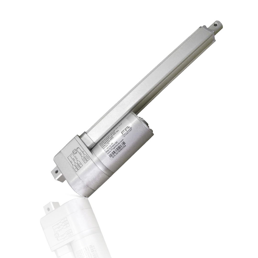
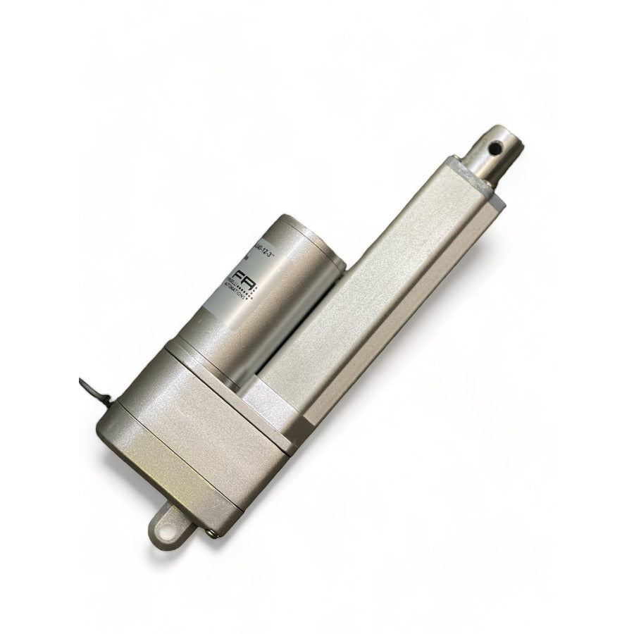
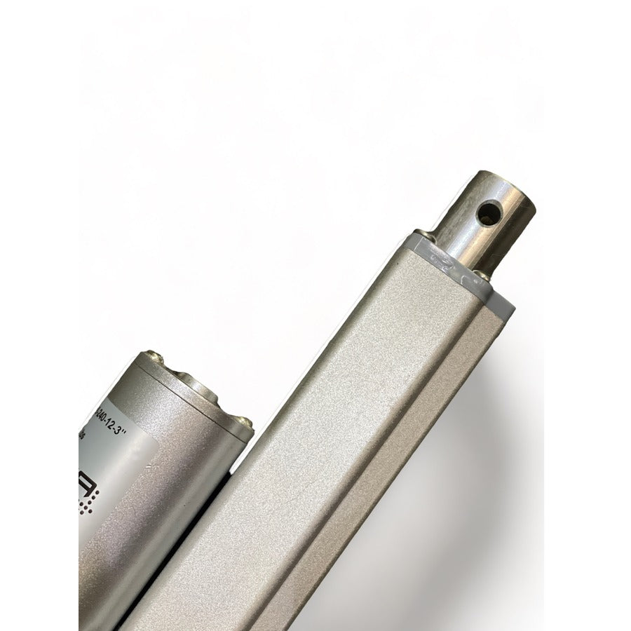
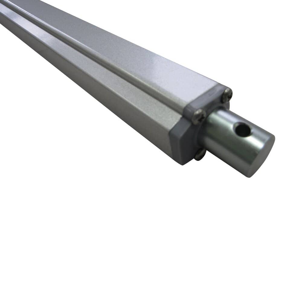
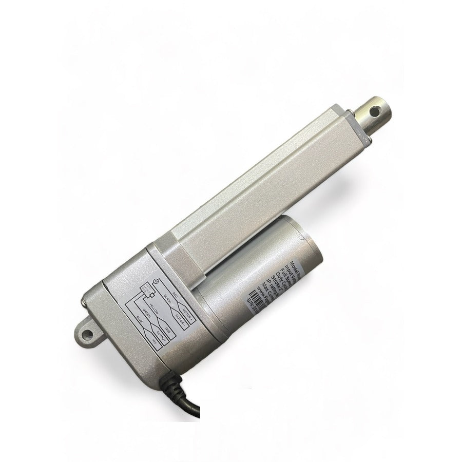
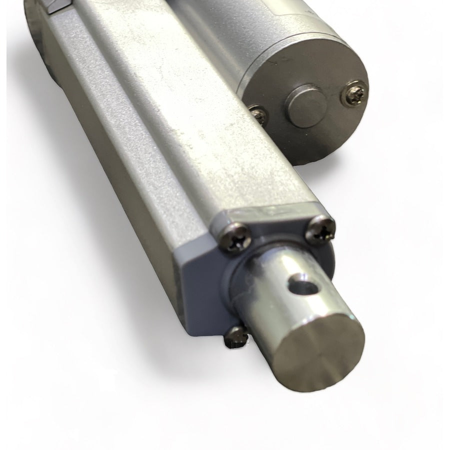
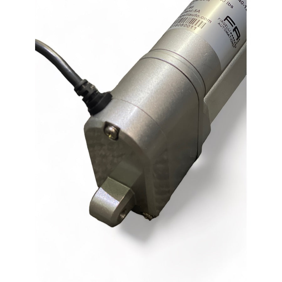
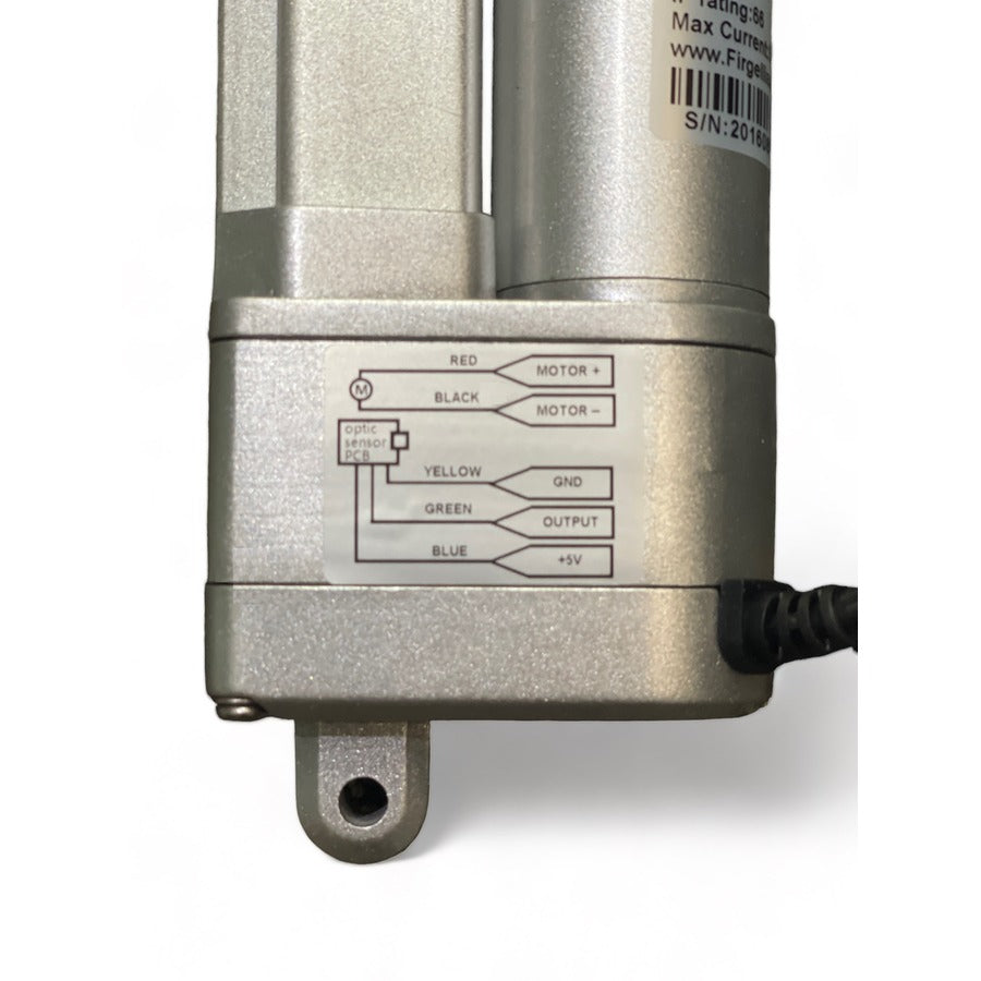
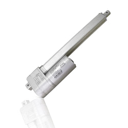
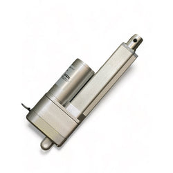
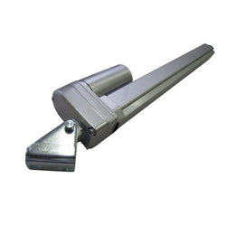
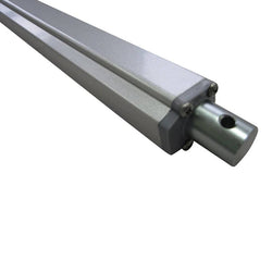
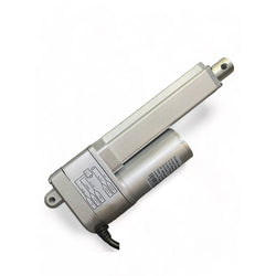
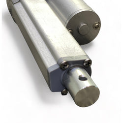
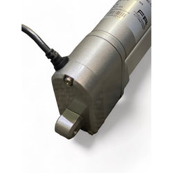
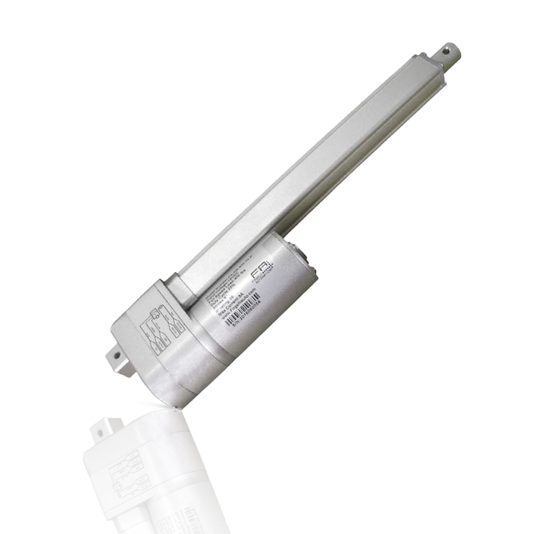
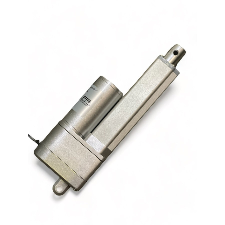
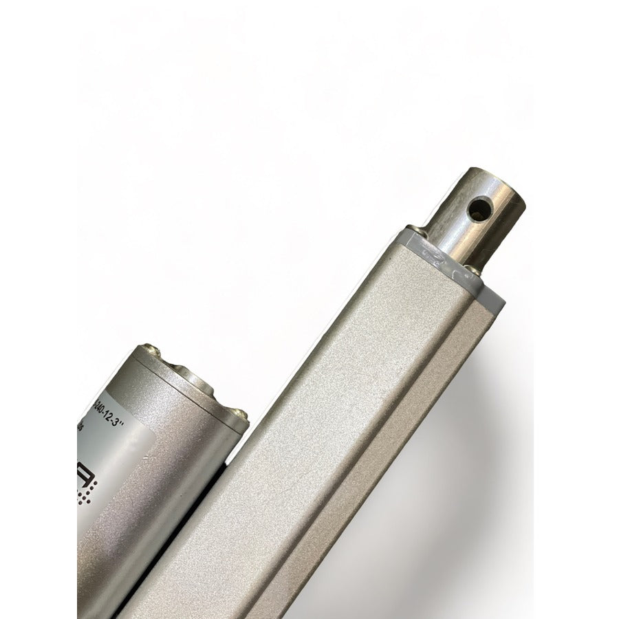
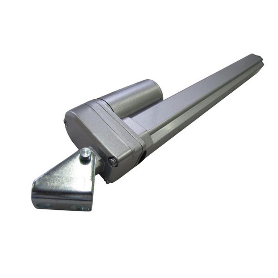
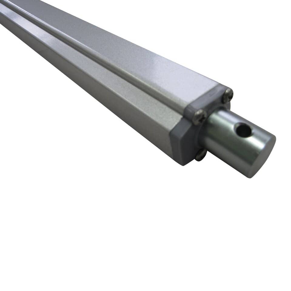
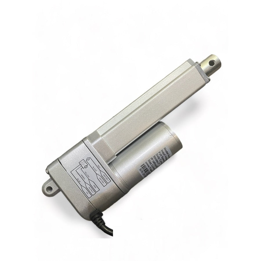
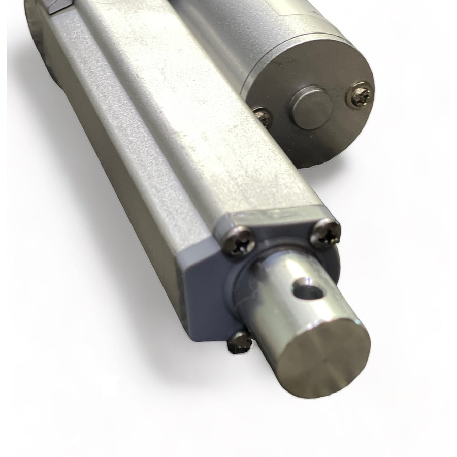
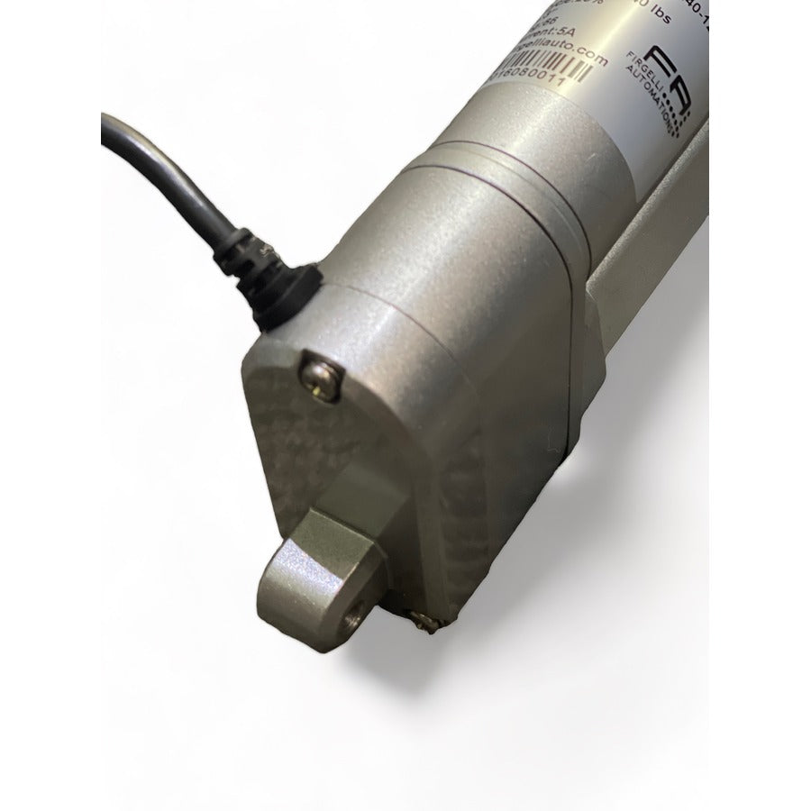
When you need to know the exact positioning of your actuators, the Optical Feedback series is what you want. This actuator comes with a built-in optical sensor that provides feedback when you need it. The Optical Feedback has no built-in controller, but does provide single-phase pulses as a feedback signal that can be input to an external controller such as an Arduino.
To move between 2 and 4 synchronized actuators, we recommend our dedicate Control board FCB-1. A video tutorial on how to use this product is available here.
CAD models of this actuator can be found under Resources/3D Files. For further information review the specifications and technical drawings down below or visit our tutorials page for instructions on how to use this actuator with switches, remotes, speed controllers, and Arduino.
Features and Benefits
- 10 hole optical encoder disk for the 200lbs and 400lbs units
- 4 slotted optical encoder disk for the 35lbs units
- 20 pulse/inch of stroke for the 35lbs (+/-5 pulses)
- 100 pulses/inch of stoke for the 200lbs and 400lbs units
- Internal limit switches automatically shut off the unit at the end of the stroke - This protects you and your equipment from possible damage.
- Huge range of stoke options as standard: 1, 3, 4, 6, 9, 12, 18, 24, and 30 inches are available - Gives you more flexibility.
- 3 Force options - 35lbs 200lbs and 400lbs for greater flexibility
- Maintenance-free - Gives you more free time to do more important things
- Accessories sold separately include: Remote Controls - Switches - Micro-Controllers - Power Supplies
- Variable Speed control - Use FA-SC2 to have full control over speed
- Works perfectly with Control board FCB-1 for the ultimate in Actuator control
Brackets
-
Fits with the MB1-P bracket
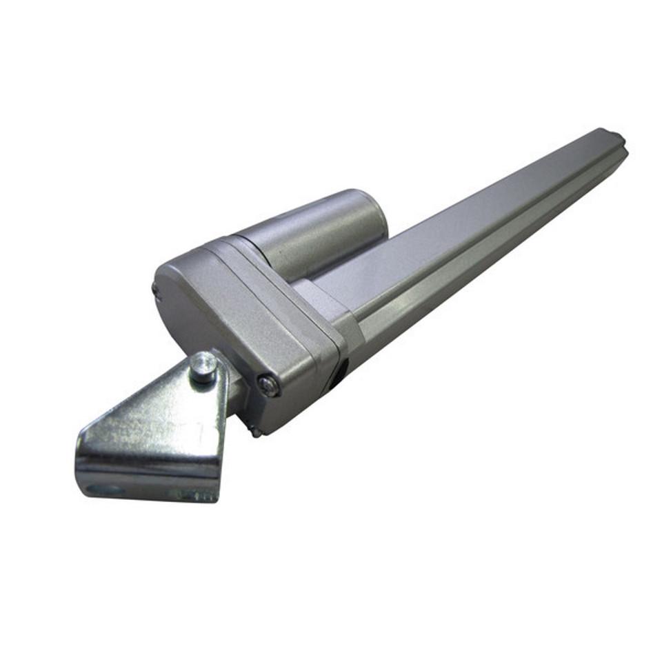
- Fits with FA-OS-IMD3 Base mounting Bracket to convert to Column Lift style Actuator except 400 lbs force.
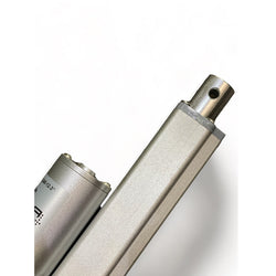
- Fits with MB10 Rod End Bracket
Specifications
Model FA-OS-35-12-(X) FA-OS-240-12-(X) FA-OS-400-12-(X) Dynamic Force 35 lbs 200 lbs 400 lb Static Force 200 lbs 500 lbs 800 lbs Speed ("/S) 2.0 .30 .30 Gear Ratio 5:1 20:1 19:1 Feedback Optical Sensor Feedback Voltage 5V Synchronous Capability Yes, with our Sync Control Board or a Microcontroller Duty Cycle 25% IP Rating IP61 Screw Type ACME Sound Rating 20 dB over Ambient Input 12v DC Max Draw 5 A Clevis End 1/4" diameter Operational Temperature -26°C/65°C (-15°F/150°) Limit Switch Built-in, non-adjustable (factory preset) Safety Certifications CE Wire Length 2.5 feet Wire Gauge 18AWG Motor, 20AWG Sensor Bracket(s) MB1-P, MB10 Technical Drawings


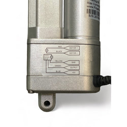
Wiring Diagram


Performance Graph

Product Video
Optical Feedback Linear Actuator Review

Comparison Video
Optical vs Classic Feedback Linear Actuator Review

Conversion to Column Actuator video

3D Model Downloads (.STEP)
35lb and 240lb Force
- 1 Inch Stroke
- 3 Inch Stroke
- 6 Inch Stroke
- 9 Inch Stroke
- 12 Inch Stroke
- 18 Inch Stroke
- 24 Inch Stroke
- 30 Inch Stroke
400lb Force
Wiring Diagram
Click here to view our wiring diagram generator to help you set up your actuator system
Tutorial
Click here to see our tutorial on how to set up an arduino with our feedback actuators.
Frequently Bought Together

MB1-P Mounting Bracket for P-series Actuator

MB6-P body brackets for P-series actuators

P-series Base Mounting Bracket

Actuator Control Board with LCD Screen Interface
- MB1-P Mounting Bracket for P-series Actuator$8.80 USD
- MB6-P body brackets for P-series actuators$9.75 USD
- P-series Base Mounting Bracket$8.65 USD
- Actuator Control Board with LCD Screen Interface$155.95 USD
