Synchronous motion between mutliple linear actuators can be vital to the success of some customer applications, one common one being two linear actuators opening a trapdoor. In order to achieve this we recommend using the dedicated Firgelli synchronous control box FA-SYNC-2 and FA-SYNC-4. However some DIYers and hackers prefer the freedom a microcontroller such as the Arduino offers and prefer instead to write their own synchronous control program. This tutorial aims to provide an overview on how to achieve this using the Optical Series linear actuator.
Foreword
This tutorial is not a rigorous treatment of the steps required to achieve synchronous control with Arduino, rather a broad overview to assist you writing your own custom program. This tutorial is advanced and assumes you are already familiar with Arduino hardware, software, and ideally have experience with pulse width modulation (PWM) signals, interrupt service routine (ISR), debouncing of sensors, and motor encoders. The example provided in this tutorial is a primitive proportional controller. Many improvements can be implemented on the following example including, but not limited to: implementing a PID control loop and scaling to more than two linear actuators. Please be aware that we do not have the resources to provide technical support for Arduino applications and will not debug, edit, provide code or wiring diagrams outside these publicly available tutorials.
Overview Synchronous Control
Synchronous control is achieved by comparing the length of two linear actuators and proportionally adjusting the speed; if one actuator starts moving faster than another we will slow it down. We can read the position of the linear actuator via the inbuilt optical encoder. The optical encoder is a small plastic disk with 10 holes in it that is connected to the DC motor such that when the motor spins the plastic disk does too. An infrared LED is directed towards the plastic disk so that as it spins the light with either be transmitted through the holes in the optical disk or blocked by the plastic of the disk. An infrared sensor on the other side of the disk detects when the light is transmit through the hole and outputs a square wave signal. By counting the number of pulses the receiver detects we can both calculate the RPM of the motor and the distance the linear actuator has travelled. The 35lb optical linear actuator has 50(+/-5) optical pulses per inch of travel while the 200lb and 400lb actuators both have 100(+/-5) pulses per inch. By comparing how far each linear actuator has extended, we are able to proportionally adjust the speed of the two actuators so that they always stay at the same length while extending.
Required Components
- Two optical linear actuators
- Two IBT-2 motor drivers
- Arduino Uno
- 12V power source
- 3 momentary buttons (not sold by Firgelli)
- Additional wiring
Wiring Diagram
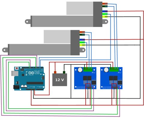
Make the above wiring connections. Always check the wire colours coming out of the linear actuator as the colouring convention may change from what is shown in the above diagram.
Quick Tutorial
If you just want to get your two linear actuators moving in synchronous simply follow these steps:
- Make the connections as shown in the wiring diagram.
- Upload and run the first program, below.
- Copy the two values output by this program into line 23 of the second program, below.
- Upload and run the second program.
- Fine tune your system by varying the variable K_p (line 37, second program). This is most easily done by attaching a potentiometer to analog pin A0 and modify thing the code to read the potentiometer and using the map() function: K_p=map(analogRead(A0), 0, 1023, 0, 20000);
The rest of this tutorial will go over in more detail some of the key features of the programs. Again we reiterate that this is not an exhaustive tutorial, rather an overview of things to consider when creating your own program.
Overview of Calibration Program
Before synchronous control can be achieved we must first calibrate the system. This involves counting the number of pulses per actuation cycle because as stated in the product specifications there is a tolerance of (+/-5)pulses per inch of travel. Upload and run the program, below. This program will fully retract the actuators (line 53) and set the optical pulse counter variable to zero it will then fully extended and fully retract (line 63 and 74, respectively). During this actuation cycle the number of pulses will be counted by the interrupt service routine (ISR), line 153 and 166. Once actuation cycle is complete the average number of pulses will be output, line 88, make note of these values for later.
https://gist.github.com/Will-Firgelli/89978da2585a747ef5ff988b2fa53904
/* Written by Firgelli Automations
 * Limited or no support: we do not have the resources for Arduino code support
 * This code exists in the public domain
 *
 * Program requires two (or more) of our supported linear actuators:
 * FA-OS-35-12-XX
 * FA-OS-240-12-XX
 * FA-OS-400-12-XX
 * Products available for purchase at https://www.firgelliauto.com/collections/linear-actuators/products/optical-sensor-actuators
 */

#include <elapsedMillis.h>
elapsedMillis timeElapsed;

#define numberOfActuators 2
int RPWM[numberOfActuators]={6, 11}; //PWM signal right side
int LPWM[numberOfActuators]={5,10};
int opticalPins[numberOfActuators]={2,3}; //connect optical pins to interrupt pins on Arduino. More information: https://www.arduino.cc/reference/en/language/functions/external-interrupts/attachinterrupt/
volatile long lastDebounceTime_0=0; //timer for when interrupt was triggered
volatile long lastDebounceTime_1=0;

int Speed = 255; //choose any speed in the range [0, 255]

#define falsepulseDelay 20 //noise pulse time, if too high, ISR will miss pulses.
volatile int counter[numberOfActuators]={};
volatile int prevCounter[numberOfActuators]={};
int Direction; //-1 = retracting
               // 0 = stopped
               // 1 = extending

int extensionCount[numberOfActuators] = {};
int retractionCount[numberOfActuators] = {};
int pulseTotal[numberOfActuators]={}; //stores number of pulses in one full extension/actuation

void setup(){
  for(int i=0; i<numberOfActuators; i++){
    pinMode(RPWM[i],OUTPUT);
    pinMode(LPWM[i], OUTPUT);
    pinMode(opticalPins[i], INPUT_PULLUP);
    counter[i]=0; //initialize variables as array of zeros
    prevCounter[i]=0;
    extensionCount[i] = 0;
    retractionCount[i] = 0;
    pulseTotal[i] = 0;
  }
  attachInterrupt(digitalPinToInterrupt(opticalPins[0]), count_0, RISING);
  attachInterrupt(digitalPinToInterrupt(opticalPins[1]), count_1, RISING);

  Serial.begin(9600);
  Serial.println("Initializing calibration");
  Serial.println("Actuator retracting...");
  Direction = -1;
  moveTillLimit(Direction, 255);
  Serial.println("Actuator fully retracted");
  delay(1000);

  for(int i=0; i<numberOfActuators; i++){
    Serial.print("\t\t\t\tActuator ");
    Serial.print(i);
  }

  Direction = 1;
  moveTillLimit(Direction, 255); //extend fully and count pulses
  Serial.print("\nExtension Count:");
  for(int i=0; i<numberOfActuators; i++){
  extensionCount[i]=counter[i];
  Serial.print("\t\t");
  Serial.print(extensionCount[i]);
  Serial.print("\t\t\t");
  }
  delay(1000);

  Direction = -1;
  moveTillLimit(Direction, 255); //retract fully and count pulses
  Serial.print("\nRetraction Count:");
  for(int i=0; i<numberOfActuators; i++){
  retractionCount[i]=counter[i];
  Serial.print("\t\t");
  Serial.print(abs(retractionCount[i]));
  Serial.print("\t\t\t");
  }
  Serial.print("\n");

  for(int i=0; i<numberOfActuators; i++){
    Serial.print("\nActuator ");
    Serial.print(i);
    Serial.print(" average pulses: ");
    pulseTotal[i]=(extensionCount[i]+abs(retractionCount[i]))/2; //takes the average of measurements
    Serial.print(pulseTotal[i]);
  }
  Serial.println("\n\nEnter these values in the synchronous control progam.");
}

void loop() {
}

void moveTillLimit(int Direction, int Speed){
  //this function moves the actuator to one of its limits
  for(int i = 0; i < numberOfActuators; i++){
    counter[i] = 0; //reset counter variables
    prevCounter[i] = 0;
  }
  do {
    for(int i = 0; i < numberOfActuators; i++) {
      prevCounter[i] = counter[i];
    }
    timeElapsed = 0;
    while(timeElapsed < 200){ //keep moving until counter remains the same for a short duration of time
      for(int i = 0; i < numberOfActuators; i++) {
        driveActuator(i, Direction, Speed);
      }
    }
  } while(compareCounter(prevCounter, counter)); //loop until all counts remain the same
}

bool compareCounter(volatile int prevCounter[], volatile int counter[]){
  //compares two arrays and returns false when every element of one array is the same as its corresponding indexed element in the other array
  bool areUnequal = true;
  for(int i = 0; i < numberOfActuators; i++){
    if(prevCounter[i] == counter[i]){
      areUnequal = false;
    }
    else{ //if even one pair of elements are unequal the entire function returns true
      areUnequal = true;
      break;
    }
  }
  return areUnequal;
}

void driveActuator(int Actuator, int Direction, int Speed){
  int rightPWM=RPWM[Actuator];
  int leftPWM=LPWM[Actuator];

  switch(Direction){
  case 1: //extension
    analogWrite(rightPWM, Speed);
    analogWrite(leftPWM, 0);
  break;

  case 0: //stopping
    analogWrite(rightPWM, 0);
    analogWrite(leftPWM, 0);
  break;

  case -1: //retraction
    analogWrite(rightPWM, 0);
    analogWrite(leftPWM, Speed);
  break;
  }
}

void count_0(){
  //This interrupt function increments a counter corresponding to changes in the optical pin status
  if ((millis() - lastDebounceTime_0) > falsepulseDelay) { //reduce noise by debouncing IR signal
    lastDebounceTime_0 = millis();
    if(Direction==1){
      counter[0]++;
    }
    if(Direction==-1){
      counter[0]--;
    }
  }
}

void count_1(){
  if ((millis() - lastDebounceTime_1) > falsepulseDelay) {
    lastDebounceTime_1 = millis();
    if(Direction==1){
      counter[1]++;
    }
    if(Direction==-1){
      counter[1]--;
    }
  }
}
Overview of Synchronous Program
Before uploading the synchronous control program, you must first copy the values output by the calibration program into line 23 and replace the current array: {908, 906} with your own values. Additionally, if you are using the 35lb linear actuator you will need to change the value of the variable in line 29 from 20 milliseconds to 8 milliseconds.
After fully retracting once (to identify the origin) you can move both linear actuators in synchronous by pressing the three buttons corresponding to extension, retraction and stop commands. The actuators will remain in synchronous even under uneven loads by comparing their relative pulse counters and adjusting speed between them to always remain in synchronous. Be advised that the current program implements a simple proportional controller, line 93, as such is subject to overshoot and oscillation around the equilibrium. You can tune this by varying the variable K_p, defined at line 37. This is most easily done by attaching a potentiometer to analog pin A0 and modify thing the code to read the potentiometer and using the map() function: K_p=map(analogRead(A0), 0, 1023, 0, 20000);
For the best results we strongly suggest removing the proportional controller and implementing a PID control loop; however this is beyond the scope of this introductory tutorial and has been omitted deliberately.
https://gist.github.com/Will-Firgelli/44a14a4f3cac3209164efe8abe3285b6
/* Written by Firgelli Automations
 * Limited or no support: we do not have the resources for Arduino code support
 * This code exists in the public domain
 *
 */

#include <elapsedMillis.h>
elapsedMillis timeElapsed;

#define numberOfActuators 2
int downPin = 7;
int stopPin = 8;
int upPin = 9;
int RPWM[numberOfActuators]={6, 11};                                  //PWM signal right side
int LPWM[numberOfActuators]={5,10};
int opticalPins[numberOfActuators]={2,3};                             //connect optical pins to interrupt pins on Arduino. More information: https://www.arduino.cc/reference/en/language/functions/external-interrupts/attachinterrupt/
volatile unsigned long lastDebounceTime[numberOfActuators]={0,0};     //timer for when interrupt is triggered
int pulseTotal[numberOfActuators]={908, 906};                         //values found experimentally by first running two-optical-actuators-sync-calibration.ino

int desiredSpeed=255;
int adjustedSpeed;
int Speed[numberOfActuators]={};

#define falsepulseDelay 20                                            //noise pulse time, if too high, ISR will miss pulses. If using 35lb actuator, set to 8ms
volatile int counter[numberOfActuators]={};
volatile int prevCounter[numberOfActuators]={};
volatile float normalizedPulseCount[numberOfActuators]={};
int Direction;                                                        //-1 = retracting
                                                                      // 0 = stopped
                                                                      // 1 = extending
float error;
int K_p=12000;                                                        //optimized experimentally. adjust this to fine tune your system
int laggingIndex, leadingIndex;                                       //index of the slowest/fastest actuator

void setup(){
  pinMode(stopPin, INPUT_PULLUP);
  pinMode(downPin, INPUT_PULLUP);
  pinMode(upPin, INPUT_PULLUP);
  for(int i=0; i<numberOfActuators; i++){
    pinMode(RPWM[i],OUTPUT);
    pinMode(LPWM[i], OUTPUT);
    pinMode(opticalPins[i], INPUT_PULLUP);
    Speed[i]=desiredSpeed;
  }
  attachInterrupt(digitalPinToInterrupt(opticalPins[0]), count_0, RISING);
  attachInterrupt(digitalPinToInterrupt(opticalPins[1]), count_1, RISING);
  Serial.begin(9600);
  Serial.println("Calibrating the origin");
  Serial.println("Actuator retracting...");
  Direction = -1;
  moveTillLimit(Direction, 255);
  for(int i=0; i<numberOfActuators; i++){
    counter[i]=0;                                                     //reset variables
    prevCounter[i]=0;
    normalizedPulseCount[i] = 0;
  }
  delay(1000);
  Serial.println("Actuator fully retracted");
}

void loop() {
  checkButtons();

  if(Direction==1){                                                   //based on direction of motion identify the leading and lagging actuator by comparing pulse counts
    if(normalizedPulseCount[0] < normalizedPulseCount[1]){
      laggingIndex = 0;
      leadingIndex = 1;
    }
    else{
      laggingIndex = 1;
      leadingIndex = 0;
    }
  }
  else if(Direction==-1){
    if(normalizedPulseCount[0] > normalizedPulseCount[1]){
      laggingIndex = 0;
      leadingIndex = 1;
    }
    else{
      laggingIndex = 1;
      leadingIndex = 0;
    }
  }

  error=abs(normalizedPulseCount[laggingIndex]-normalizedPulseCount[leadingIndex]);
  if(Direction!=0){
    adjustedSpeed=desiredSpeed-int(error*K_p);
    Speed[leadingIndex]=constrain(adjustedSpeed, 0, 255);               //slow down fastest actuator
    Speed[laggingIndex]=desiredSpeed;
  }
  for(int i=0; i<numberOfActuators; i++){
    Serial.print("  ");
    Serial.print(Speed[i]);
    Serial.print("  ");
    Serial.print(normalizedPulseCount[i]*1000);
    driveActuator(i, Direction, Speed[i]);
  }
  Serial.println();
}

void checkButtons(){
  //latching buttons: direction remains the same when let go
  if(digitalRead(upPin)==LOW){ Direction=1; }                           //check if extension button is pressed
  if(digitalRead(downPin)==LOW){ Direction=-1; }
  if(digitalRead(stopPin)==LOW){ Direction=0; }
}

void moveTillLimit(int Direction, int Speed){
  //function moves the actuator to one of its limits
  for(int i = 0; i < numberOfActuators; i++){
    counter[i] = 0;                                                     //reset counter variables
    prevCounter[i] = 0;
  }
  do {
    for(int i = 0; i < numberOfActuators; i++) {
      prevCounter[i] = counter[i];
    }
    timeElapsed = 0;
    while(timeElapsed < 200){                                           //keep moving until counter remains the same for a short duration of time
      for(int i = 0; i < numberOfActuators; i++) {
        driveActuator(i, Direction, Speed);
      }
    }
  } while(compareCounter(prevCounter, counter));                        //loop until all counters remain the same
}

bool compareCounter(volatile int prevCounter[], volatile int counter[]){
  //compares two arrays and returns false when every element of one array is the same as its corresponding indexed element in the other array
  bool areUnequal = true;
  for(int i = 0; i < numberOfActuators; i++){
    if(prevCounter[i] == counter[i]){
      areUnequal = false;
    }
    else{                                                               //if even one pair of elements are unequal the entire function returns true
      areUnequal = true;
      break;
    }
  }
  return areUnequal;
}

void driveActuator(int Actuator, int Direction, int Speed){
  int rightPWM=RPWM[Actuator];
  int leftPWM=LPWM[Actuator];
  switch(Direction){
    case 1:       //extension
      analogWrite(rightPWM, Speed);
      analogWrite(leftPWM, 0);
      break;
    case 0:       //stopping
      analogWrite(rightPWM, 0);
      analogWrite(leftPWM, 0);
      break;
    case -1:      //retraction
      analogWrite(rightPWM, 0);
      analogWrite(leftPWM, Speed);
      break;
  }
}

void count_0(){
  //This interrupt function increments a counter corresponding to changes in the optical pin status
  if ((millis() - lastDebounceTime[0]) > falsepulseDelay) {             //reduce noise by debouncing IR signal with a delay
    lastDebounceTime[0] = millis();
    if(Direction==1){
      counter[0]++;
    }
    if(Direction==-1){
      counter[0]--;
    }
    normalizedPulseCount[0]=float(counter[0])/float(pulseTotal[0]);
  }
}

void count_1(){
  if ((millis() - lastDebounceTime[1]) > falsepulseDelay) {
    lastDebounceTime[1] = millis();
    if(Direction==1){
      counter[1]++;
    }
    if(Direction==-1){
      counter[1]--;
    }
    normalizedPulseCount[1]=float(counter[1])/float(pulseTotal[1]);
  }
}
Using Bullet 36 and Bullet 50 Actuators in Synchronous
In addition to our Optical Series linear actuator we also offer two offer linear actuators with inbuilt encoders: the Bullet 36 Cal. and the Bullet 50 Cal, both of which have an internal quadrature Hall Effect encoder. The Hall Effect encoder works on the same principle as the optical encoder however instead of using light it utilizes magnetism. Furthermore being a quadrature encoder it has two signal outputs, each out of phase by 90 degrees. As such you need to use an Arduino board with 4 or more interrupt pins (the Arduino Uno only has two) and modify the code to process input from two signals per actuator. Furthermore, the debounce time variable, falsepulseDelay will need to be tuned along with K_p.
Tips for Writing Your Own Program
More than two linear actuators
When using two or more linear actuators the Arduino Uno will no longer work as it only has two interrupt pins available. You will need to use an Arduino board with the approriate number of interrupt pins available, more information: https://www.arduino.cc/reference/en/language/functions/external-interrupts/attachinterrupt/
Secondly in the interest of efficiency it is advisable to vectorize your programming utilizing arrays and for() loops to iterate over each actuator.
Debouncing
As with many sensors it is important to be cognisant of bouncing signals. As with mechanical switches, encoders can also suffer from bouncing. In the above example the debouncing process has been handled by a simple delay (defined by the falsepulseDelay variable), it is important to handle this in any software changes you make or with physically circuitry to filter out the bouncing noise.
Handling roll over
If you modify the code be aware of rollover when dealing with the millis() function. Both millis() and the lastDebounceTime array are declared as unsigned long variables meaning they can store values up to 4,294,967,295 (32^2-1). This translates to roughly a rollover period of 49.7 days. The current program is designed to handle rollover in the ISR (interrupt service routine) functions: count_0 & count_1, however if you modify this program be sure to correctly handle the variable rollover, else your program will crash after ~49.7 days of continuous use. For more information refer to: https://www.norwegiancreations.com/2018/10/arduino-tutorial-avoiding-the-overflow-issue-when-using-millis-and-micros/


