-
Home -
Wiring Diagram Generator | Actuator P...
Linear Actuator Wiring Diagrams Generator
Recommended Products
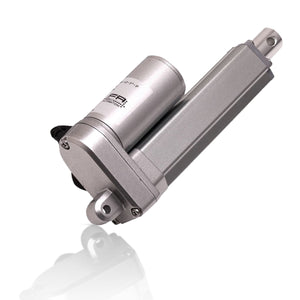
P-Series Linear Actuators
In Stock
From
$136.95USD
From
$136.95USD
LEARN MORE
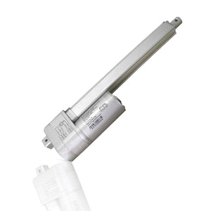
Optical Feedback Actuators
In Stock
From
$159.99USD
From
$159.99USD
LEARN MORE
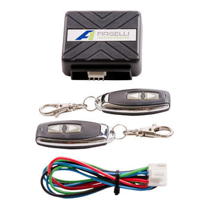
2 Channel Remote Control System
In Stock
$58.00USD
$58.00USD
LEARN MORE
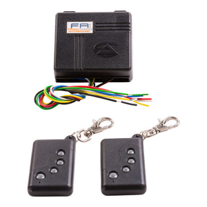
Four Channel Remote Control System - 4CH-RC
In Stock
$69.00USD
$69.00USD
LEARN MORE
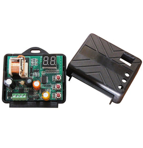
Overcurrent Protection System - FA-POCT
Out of Stock
$18.75USD
Sold Out
$18.75USD
Sold Out
LEARN MORE
External Limit-Switch Microswitch Kit for Actuators
In Stock
$19.80USD
$19.80USD
LEARN MORE
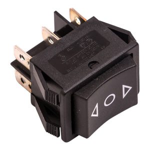
Rocker Switches for Linear Actuators
In Stock
$4.20USD
$4.20USD
LEARN MORE
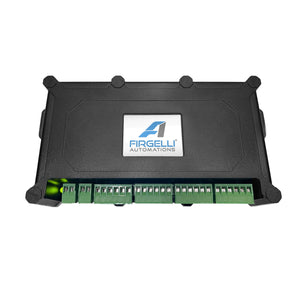
Actuator Control Board with LCD Screen Interface
Out of Stock
$225.95USD
Sold Out
$225.95USD
Sold Out
LEARN MORE
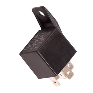
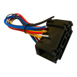
12 Volt Single-Pole Double-Throw Relay SPDT Relay 20Amp
In Stock
$9.00USD
$9.00USD
LEARN MORE
$8.60USD
LEARN MORE
$8.80USD
LEARN MORE
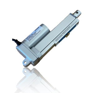
Adjustable Stroke Linear Actuators
In Stock
$154.95USD
$154.95USD
LEARN MORE
Super Duty Actuators
In Stock
From
$149.95USD
From
$149.95USD
LEARN MORE

Utility Linear Actuator
In Stock
$149.95USD
$149.95USD
LEARN MORE

Bullet Series 35 Cal. Linear Actuators
In Stock
From
$169.00USD
From
$169.00USD
LEARN MORE
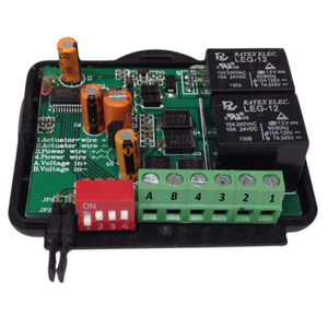
Speed Controller for Linear Actuators
In Stock
$38.00USD
$38.00USD
LEARN MORE

Speed Controller for Actuators and Motors
In Stock
$19.00USD
$19.00USD
LEARN MORE
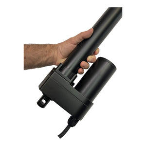
Power Max Heavy Duty Actuators - 900 to 1500lbs Force
In Stock
From
$309.99USD
From
$309.99USD
LEARN MORE
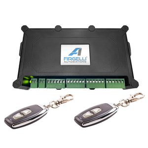
Remote control Actuator Controller with LCD Screen
Out of Stock
$265.95USD
Sold Out
$265.95USD
Sold Out
LEARN MORE

