Potentiometers
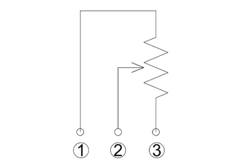
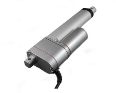
Potentiometers, which are variable resistors, are used in linear actuators to provide positional feedback base on how their resistance changes. Linear actuators that use potentiometers for feedback, like our Feedback Rod Linear Actuator, will consist of the 3 additional wires like shown below, wire 1 for the input voltage, wire 2 is the variable resistor, and wire 3 is for ground. You can read the output of the potentiometers by measuring the voltage between wire 2, the output, and ground, which will provide an indication of the absolute position of the linear actuator. To utilize this feedback, you’ll need to make use of some type of microcontroller, like an Arduino, to read this positional value as the actuator moves.

Positional Feedback from a Potentiometer
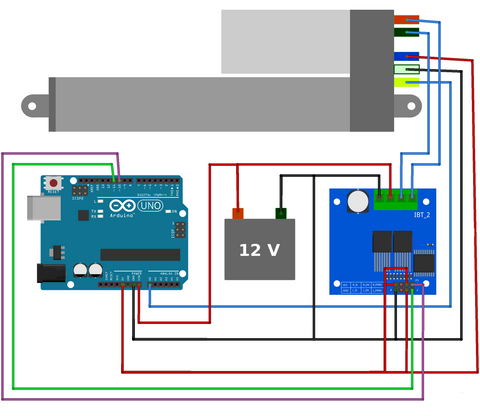
As the variable resistor of the potentiometer changes as the linear actuator moves, the voltage difference between wire 2 and ground will change. Because of this, the feedback can easily be handled in the software of a controller, like an Arduino, as you can simply compare the output voltage of wire 2 to ground. Using an Arduino, this can simply be done by using an analog in pin of a microcontroller and using the analogRead() function to read the voltage from wire 2. An example of how to connect an Arduino to a linear actuator with potentiometer feedback is shown below.

The analog in pins of the Arduino are analog-to-digital converters (ADC), which will convert the analog voltage on wire 2 to a 10-bit ADC value that will be between 0 to 1023. A 10-bit ADC value means the converter will translate the analog signal into 2^10 or 1024 distinct values ranging from 0 to 1023. Not all microcontrollers are 10-bit ADC, some are 8-bit or 16-bit, and the greater the number of bits the greater the resolution of the ADC. Once you have converted the analog signal into a digital value, to determine a position value in terms of stroke length, like in inches, you’ll need to find the exact analog range of your particular linear actuator as it may not range from 0 to 1023. This is because of the gearbox inside the actuator preventing the potentiometer fully rotating to its limit and means you’ll need to determine this range manually. For the coding example below, the 4” stroke length Feedback Rod Linear Actuator had an analog value of 44 at 0” and an analog value of 951 at 4”. Using these values, you can use ratios to determine the stroke length value like below:

This can be simplified into Stroke Length = 0.00441*(Analog Value – 44), like in the coding example below. How often you read this analog value in the code of your microcontroller is another important consideration. In the code example below, the Arduino reads the potentiometer and updates the position value as long as the actuator is moving. But you could also make use of internal timers to update the position value over a set interval of time or you could simply place the potentiometer read function inside of the main loop of the code and continuously update the position value. Although the latter is not recommended if you plan to use your controller to perform multiple individual functions.
https://gist.github.com/OMikeGray/4dec9e075a8fe41efaea001fa1e98d70
float pos;                      // Actuator Position
float conNum = 0.00441;         // Constant to convert ADC to Inches
                                // Equal to (951 (ADC at 4") - 44 (ADC at 0")/4")^-1
void setup() {
  pinMode(A1, INPUT);         // Configure Analog In pin 1 as an Input
  pinMode(10, OUTPUT);        // Configure pin 10 as an Output
  pinMode(11, OUTPUT);        // Configure pin 11 as an Output
  pinMode(2, INPUT_PULLUP);   // Input for Button
  pinMode(3, INPUT_PULLUP);   // Input for Button

  Serial.begin(9600);
}

void loop() {
  if(digitalRead(2) == HIGH & digitalRead(3) == LOW){
   // Retract Actuator
    analogWrite(10, 0);
    analogWrite(11, 255);
    pos = readPotentiometer(); // Print position value to the Serial Display
    Serial.println(pos);
    delay(1);
  }
  else if(digitalRead(2) == LOW & digitalRead(3) == HIGH){
    // Extend Actuator
    analogWrite(10, 255);
    analogWrite(11, 0);
    pos = readPotentiometer();
    Serial.println(pos);  // Print position value to the Serial Display
    delay(1);
  }
  else{
    // Stop Actuator
    analogWrite(10, 0);
    analogWrite(11, 0);
  }
}

/*Function to Read Potentiometer and Convert it to Inches*/
float readPotentiometer(void){
  float pos;
  pos = conNum*(analogRead(A1) - 44); // 44 ADC is equal to 0"
  return pos;
}
Dealing with Electrical Noise
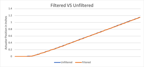
One drawback of feedback from the potentiometer is that it can be affected by electrical noise and may make your positional value unstable. One way to overcome this is to use a digital filter to remove the electrical noise and achieve stable results. There are few different types of filters that can be used from exponential filters to high-pass and band-pass filters each with their own benefits, but for many applications with linear actuators, simply using a running average of the positional value will work. A running average is simply the average of the last X amount of measurements to smooth out the input signal. The exact number of measurements you want to average will depend on your application and you may need to play around with this number to determine what works best. A few things to be aware of, if you have too few measurements in your average, your signal will still be noisy, but if you have too many measurements, your results will lag too far behind the actual position of the actuator to be useable. It is finding a balance between too few and too many measurements that will make your filter effective. Below is a plot showing the effect of a running average filter versus the actual input signal.

The code used to implement the running average is shown below, it uses an average of 3 measurements to smooth the input signal. Three measurements were chosen because there wasn’t a lot of noise in actual input signal, so only a few measurements were needed to smooth out the value. If there was more noise in the input signal, a larger number of measurements would be needed. In situations where there is a lot of inductive components (i.e. motors) electrical noise will be a much larger problem.
https://gist.github.com/OMikeGray/b13f156c080a100a89e5bbd541d0565e
float readPotentiometer(void){
  int sum = 0;                         // Sum of Measurements
  static int j = 0;
  valuesToAverage[j] = analogRead(A1); // Place Measurement in Buffer with Previous Values
  for(int i = 0; i < numMeasure; i++){
    sum +=valuesToAverage[i];          // Add Up all Muasurements
  }
  if(j < numMeasure-1){j++;}
  else{j = 0;}
  return conNum*((sum/numMeasure) - 44); // Divide by number of measurements
}                                        // & Convert to Inches
Utilizing Feedback for Automation
The great thing about implementing feedback into your design is that it allows you to create a self-automated system that knows where to be for a given input. To utilize potentiometer feedback in an automated system you can simply compare your desire extended length of your linear actuator to the actual position that is given by the potentiometer. Then you simply need to tell your actuator to extend or retract accordingly. Although utilizing potentiometer feedback in an automated system does have a few issues you may need to overcome. One is the issue of electrical noise, which was discussed above, the other is being able to achieve repeatable results. As potentiometers generally are not as sensitive to smaller movements of the linear actuator, compared to the other feedback options, this makes achieving precise repeatable results more difficult. In practice, this means you’ll have a margin of error around your desired position, which may be acceptable for your given application. If you do not need very precise positionings or are replacing a manual switch with a microcontroller to automate your system, positional feedback from a potentiometer will be accurate enough for you. If you do need accurate positioning from your linear actuator, then you may need to consider other feedback options for your linear actuator or add additional components to provide more reliable results. These components include sensors or external limit switches which may give you a better indicator of absolute position.

Not being able to achieve repeatable results is also an issue when your controlling multiple linear actuators. As the output signal of the potentiometer is easily affected by electrical noise, including electrical noise from the other actuators, and is dependent on the input voltage to the potentiometer, ensuring multiple linear actuators move simultaneously can be challenging. Utilizing digital filters, guaranteeing stable input voltage to the potentiometer, and having the output signal wires running away from other inductive components will all help ensure more repeatable results. Although, if you do want to run multiple actuators simultaneously, it might be better to check out the other feedback options for linear actuators.