Pulse-width Modulation (PWM)
1. The Basics of Pulse-width Modulation (PWM)
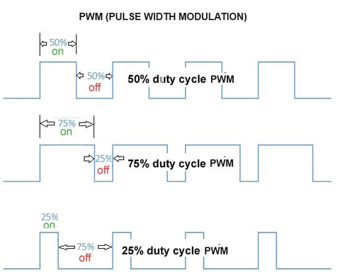
Pulse-width Modulation (PWM) serves as a digital method that simulates an analog signal to control the power delivery to electronic devices. In its essence, PWM swiftly toggles the power between ON and OFF states at a set frequency, enabling the management of average power, which offers a plethora of control possibilities.2. The Science Behind PWM
When we break it down, PWM functions quite similarly to a light switch. The concept is rooted in toggling a signal on and off rapidly. With varying intervals, one can manipulate and emulate different levels of power output. Hence, in the vast electronics landscape, PWM efficiently manages the average power a device perceives and ultimately receives.3. DC Motors and PWM: A Match Made in Electronics
PWM’s flexibility allows it to control a myriad of DC motors:• Brushed DC Motors: These motors are straightforward and react directly to PWM signals, translating them into varying speeds.
• Brushless DC Motors (BLDC): A tad more sophisticated, BLDC motors require customized PWM sequences for each of their coils.
However, it’s pivotal to understand that while PWM’s foundational principles are universally applicable, individual motor designs can profoundly influence their response to PWM.
4. Intricacies of Motor Characteristics: Size, Inertia, and Torque
Every motor is unique, and PWM signals must be fine-tuned to cater to these nuances:• Size and Inertia: Motors with a larger physical size or higher inertia often exhibit a delayed response to abrupt PWM changes. In such cases, one might need to tweak the PWM frequency or duration to ensure smooth operation.
• Torque: High-torque motors may necessitate more potent or prolonged PWM signals. It’s crucial to calibrate the PWM signal to align with a motor’s torque to guarantee optimal performance.
These adjustments are essential for ensuring that the motor responds harmoniously to the PWM signal, paving the way for efficient and reliable operations.
5. Dissecting a Typical PWM Signal
A standard PWM signal can be visualized as a square wave, comprising:• Frequency: This determines how swiftly the signal oscillates between its ON and OFF states. It’s quantified in Hertz (Hz).
• On-Time: Represents the duration within a cycle where the signal remains active or ON. By varying this aspect, one can effectively regulate the power directed towards a motor, and hence, its behavior.
6. The FIRGELLI FCB-1: A Real-world Example of PWM Mastery
A tangible representation of PWM’s potential is epitomized by the FIRGELLI FCB-1:• Speed Control: The FCB-1 harnesses PWM’s power to dictate the precise speed of actuators. This ensures smooth and efficient operation in various applications.
• Synchronization: One of the FCB-1’s crowning features is its prowess in synchronizing up to four actuators. Through meticulous PWM control, it ensures that each actuator operates concurrently, providing a harmonized movement.
